
Transformer is assembly of many parts and each part performs a specific task. Now, we will see them.
1.Main Tank :- It is a closed vessel in which the winding, core and oil is placed. It is the main frame on which all other parts are installed. The size of main tank depends upon the KVA Rating of transformer.
2.Winding :- On the core, number of turns of wire (usually Enameled copper or aluminum conductor ) is wound to form a coil. This is called winding. Hard drawn copper of high conductivity in the form of round /strip conductors with paper or enamel insulation is used.
There are two types winding :- a) Concentric winding b) Sandwich Winding. Different windings have different characteristics and they are used accordingly.
3.Core :- The core is made up of silicon steel or cold rolled grain oriented (CRGO) in the form of laminations of 0.25 – 0.35 mm in thickness with insulated coating of carlite.
There are two types of core :- a) Core type b) Shell Type
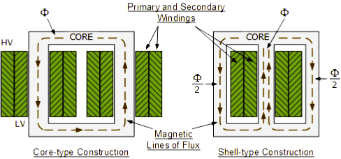
a) Core Type :- In this type, there is only one iron path and windings are wound over opposite limbs.
b) Shell Type :- This type of core has two parallel magnetic path into which the flux of central limb can divide.
4.Radiator :- To dissipate the heat generated in the transformer to work more efficiently the radiators are used. The heat generated in the core and winding transfered to the oil in which they are drowned, then that heated oil passed through tube or finses which increases the surface area that helps to boost the rate of heat dissipation.
Different cooling methods of Transformer used with radiators :-
a) Oil Natural Air Natural (ONAN):- Cooling oil or transformer oil is circulated naturally and air strikes naturally. No other equipment used to cool.
b) Oil natural Air Forced (ONAF) :- Oil circulates naturally but fans are used to strike the air on radiators in order to increase the heat dissipation rate.
c) Oil Forced Air Forced (OFAF) :- In this type of method both are operated forcefully by using some machineries (i.e. Pump, Fans etc ). This is the most efficient method to cool down the transformer.
d) Oil Forced Water Forced (OFWF) :- This type of method used where too much ventilation is required. Because in this method oil as well water around the radiators are circulated by some pumping mechanism. So, definitely the rate of heat dissipation is maximum.
5.Conservator Tank :- To maintain the oil level in main tank of transformer conservator tank is used.
It’s cylindrical vessel made up of structural steel. It’s capacity is approximately 10% of the main tank and filled with 1/3rd of its volume. It’s placed above the transformer main tank level.

Whenever, oil in the main tank expand or contract due to the heating and cooling down of oil respectively the level of oil changes accordingly. To maintain this level automatically, conservator tank due to gravity as it is placed on top.
6.Breather :- It is placed with conservator tank to remove moisture whenever the conservator inhale the air from nature. when the level of oil in conservator tank and main tank decreases the conservator inhale and when the oil heats up the oil level increases and the air present in the conservator tank exhale the air.
A breather consist of a chemical compound named Cobalt chloride (CoCl2). That is used to show the presence of moisture. This property is used in breather. It’s blue colour show the good condition and it turns into pink colour when in poor condition. Sometimes, you might see a breather in dark black colour.

7.Bushing :- We can’t connect the conductor directly to the winding because it may shorted with each other or earthed. So, a bushing is device which is used to make the connection between windings and external conductors.
8.Oil Level Indicator :- Plain or prismatic glass is generally used as oil level indicator. It is used to measure the oil level of Conservator. There is parallel connection of indicator with tank along with it’s dia. So that we can clearly see the current oil level in the conservator.
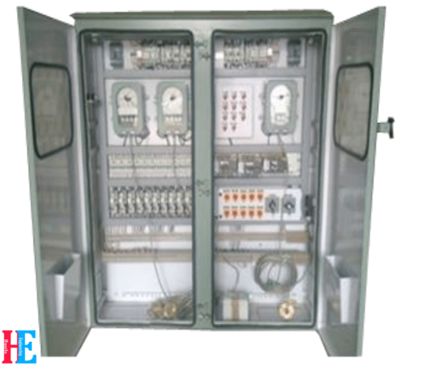
9.Marshalling Box :- It is the main box situated near the transformer in which all the external connections (like; Circuit breaker, C.T. , P.T. ,OTI, WTI etc.) are made.
10.Oil Temperature Indicator (OTI) :- It is a device used to measure oil temperature present in the main tank. When temperature of oil increases more than preset value (i.e. Alarm at 80°C and Trip at 90° app.) it gives signals to the relays and panel to take necessary step. It is installed in Marshalling box.

11.Winding Temperature Indicator (WTI) :- It is a device which is used to measure winding temperature. This help to protect the transformer when temperature increases more than predetermined safe value ( i.e. Alarm at 85°C and Trip at 95°C app.) Then, it gives command to take the panel and ralays to take required step accordingly. This is placed in Marshalling box.
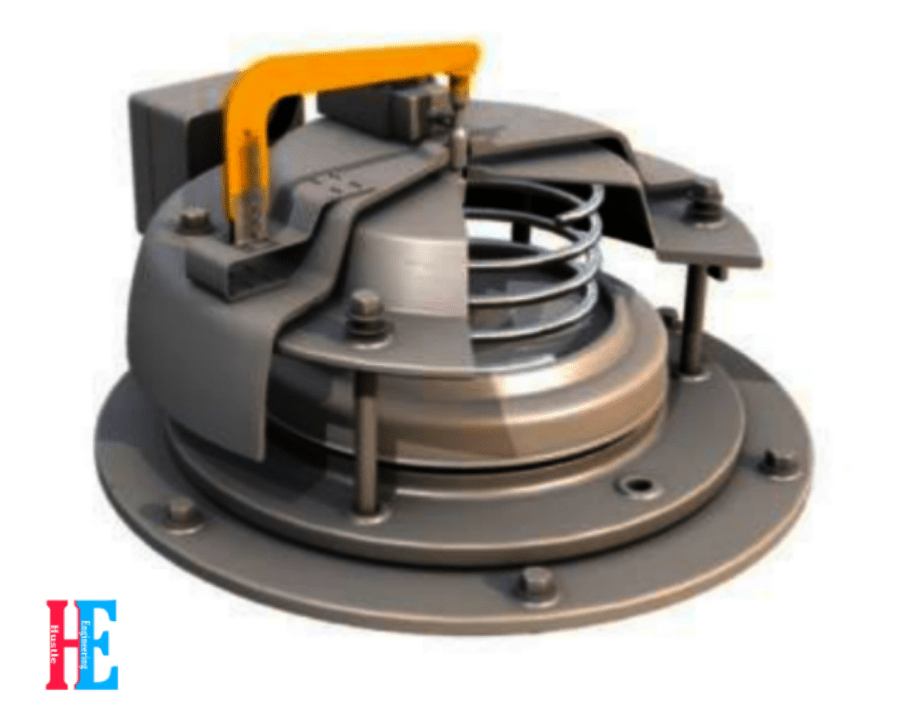
12. Pressure Release Valve (PRV) :- When pressure inside main tank due to internal fails or other reason or If short circuit occur in the transformer then the arc vaporize the oil and heavy pressure is built. This pressure could harm the main tank (or may blast the main tank). so, it’s necessary to release such harmful pressure. This releasing of pressure is done by PRESSURE RELEASE VALVE (PRV). It has stainless steel diaphragm which vets lifted under high pressure condition to reduce pressure. It is mounted on top of the tank.
13.On Load Tap Changer (OLTC) :- To maintain the output voltage at constant by changing the tapping without interrupting the output supply. This primary side voltage fluctuate or changes due to some reasons ( like capacitance effect in Transmission). So, to maintain the secondary voltage the OLTC is used. Number of tappings (Usually 17 tappings) are brought out and they are connected through reactors and there is a selector switch to switch among the tappings. This selector switch is either is operated manually or automatically by using automation technology. There are two parallel switch to avoid interruption. Means if you want to change the tapping then, second switch is connected to that tap meanwhile first switch is still connected to the output. When second switch is connected to the another tap completely then first switch get disconnect. This is how it avoid intrupption.

OLTC is always installed on high voltage (HV) side due to 2 reason :-
- High voltage (HV) windings are wound over low voltage(LV) winding, so it is easy to take out the tappings.
- As compare to LV side, HV side current is lower. So, arc development chances are very less. So, due to this, there is less chance of any external faults due to arcing.
